Setting up Raspberry Pi3
Installing Tizen Studio
If you have already installed Tizen Studio 3.0 and installed the 5.0 Mobile profile for the Main SDK and the IoT Setup Manager, IoT-Headed-5.0 and IoT-Headless-5.0 profiles for the Extension SDK, you can skip this section.
Otherwise, to install Tizen Studio and the required profiles for IoT development:
-
Download and install the correct version of Tizen Studio 3.0 (or later) for your operating system from Tizen developer site.
-
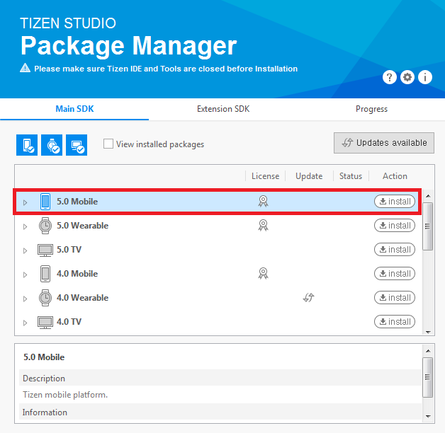
Open the Tizen Studio Package Manager, select the Main SDK tab, and install the 5.0 Mobile profile:
-
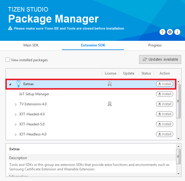
Select the Extension SDK tab and Extras. Extras includes IoT Setup Manager and IoT-Headless-5.0 profiles:
Note
Extension SDK should be updated to the latest version.
Flashing Tizen Images with IoT Setup Manager
IoT Setup Manager helps you to easily install Tizen on your IoT device using your computer. It helps to get your device running and connected to the local network. After your device is connected to the local network, you can start developing and testing the Tizen IoT applications.
Prerequisites
You must have the binary images in your computer. You can download the binary images from:
- Boot image: tizen-unified_20181024.1_iot-boot-arm64-rpi3.tar.gz
- Platform image:
- Headless (without display): tizen-unified_20181024.1_iot-headless-2parts-armv7l-rpi3.tar.gz
Launch IoT Setup Manager
You can launch the IoT Setup Manager with or without using Tizen Studio:
Launch using Tizen Studio
From Tizen Studio, you can launch the IoT Setup Manager in the following two ways:
-
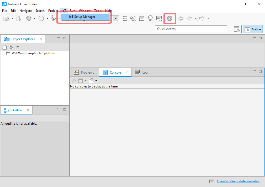
On the menu bar, go to IoT > IoT Setup Manager.
-
On the toolbar, click the IoT Setup Manager icon as shown in the following image:
Launch without using Tizen Studio
During installation, the Package Manager creates shortcuts for IoT Setup Manager, which are used to launch the IoT Setup Manager as a standalone application. To launch the IoT Setup Manager for:
-
Windows, go to Start Menu > Programs > Tizen Studio > Tools > IoT Setup Manager.
-
Ubuntu, go to Dash (equivalent to Start Menu) > Applications > IoT Setup Manager.
Flashing an SD Card using IoT Setup Manager
To flash Tizen on your SD card using the IoT Setup Manager:
-
Create a profile:
-
Click Create to create a profile. The Edit Profile window appears.
-
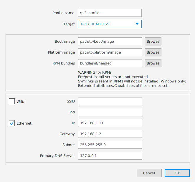
Provide the required information such as target, local paths to boot and platform image, and so on.
- Profile name: Enter a profile name, for example, RPI3_Headless
- Target: RPI3_HEADLESS
- Boot image or platform image: The local paths of the boot and platform images, which you download from Prerequisites.
- ROM bundles:
- Download tizen_5.0_rpi3_bundles.zip and unzip the file.
- Add the bundle directory just unzipped, i.e. tizen_5.0_rpi3_bundles/, to the Bundles panel.
- ROM bundles: Left as blank
- WiFi: Clear
- Ethernet:
- IP: 192.168.1.11
- Gateway: 192.168.1.2
- Subnet: 255.255.255.0
- Primary DNS Server: 127.0.0.1
- Click OK to save.
-
-
Select the SD card on which you want to burn Tizen:
-
Insert your SD Card into your computer.
-
Select the appropriate SD Card from the drop-down list (for example,
/dev/sdxon Ubuntu andF:on Windows).Note
Currently, the USB SD card reader is only supported. The internal PC SD slot is not supported. Also, if the Select Drive does not show anything, detach and insert the SD card again into the computer.
-
-
Burn Tizen on your SD Card:
- Click Burn to burn Tizen to your SD Card. This takes about two minutes to complete.
Setting up Raspberry Pi 3
Connecting the board to the PC
To configure the Raspberry Pi 3 board:
-
Insert the SD card, in which Tizen IoT binaries and the drivers are flashed into the Raspberry Pi board.
-
For the serial communication connection:
-
Connect the host computer to the Pi with a UART-to-USB dongle such as PL2303 or FT232 USB UART board.
To use the PL2303, connect the Raspberry Pi TXD0 pin (pin 8) to RXD on the UART board, RXD0 (pin 10) to TXD on the UART board, and the ground (pin 6) to GND on the UART board, and set the jumper switch to 3.3V (pin 1).
Note
Before using a UART-to-USB dongle, familiarize yourself with any hardware limitations it has by visiting the manufacturer’s website.
-
Execute a terminal program such as Minicom or PuTTY.
-
Minicom example:
Minicom can be used in Linux computer. Run the following command to run Minicom:
$ sudo minicom -c onTo configure Minicom:
- Go to the Minicom configuration settings menu by consecutively pressing
Ctrl + A,Z, andO(the letter O). - In the
Serial Devicefield, set the correct USB port for serial communication. The format is/dev/ttyUSBXwhereXequals the number of the port. - Modify the
Hardware Flow Controlfield toNo.
+-----------------------------------------------------------------------+
| A -    Serial Device      : /dev/ttyUSBX                              |
| B - Lockfile Location     : /var/lock                                 |
| C -   Callin Program      :                                           |
| D -  Callout Program      :                                           |
| E -    Bps/Par/Bits       : 115200 8N1                                |
| F - Hardware Flow Control : No                                        |
| G - Software Flow Control : No                                        |
In the serial shell, log in with
root/tizen:localhost login: root Password: tizen Welcome to Tizen - Go to the Minicom configuration settings menu by consecutively pressing
-
PuTTY example:
Download PuTTY from the Internet and launch PuTTY.
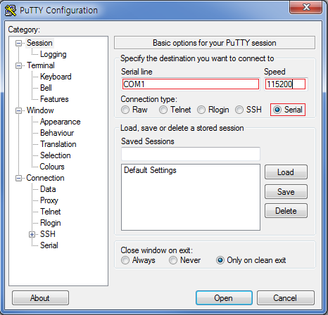
To configure PuTTY:
- Select
Serialconnection type. - Enter the serial line number for the board connected to your computer (it can be COM
NwhereNis a natural number such as COM1, COM4, and so on) in theSerial linefield. - Type 115200 in the
Speedfield. - Click
Open.
In the serial shell, log in with
root/tizen:localhost login: root Password: tizen Welcome to Tizen - Select
-
-
-
For the SDB connection:
-
Connect the host computer to the Pi through an Ethernet cable.
Note
If Ethernet ports are not available in the host computer or the Pi, you can also use an
Ethernet-to-USBdongle. -
Set a new network interface in the host computer as shown in the following figures. This is a one time activity:
- Linux computer:
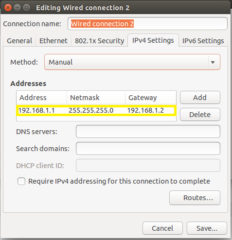
- Windows computer:
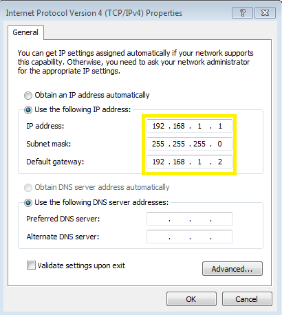
If you are using the Ethernet-to-USB dongle, you must install the proper driver for the dongle. If the network cable is connected correctly, you can find a new connection in Network and Sharing Center. In the new connection, enter Properties of IPv4, and configure as shown in the Windows computer figure.
-
-
Verify the IP address for eth0.
ifconfigIf the IP address for eth0 is 192.168.1.11, go to step 5. If not, set an IP address for the SDB connection in the serial shell of the Pi using the
ifconfigcommand:ifconfig eth0 192.168.1.11 -
Connect Smart Development Bridge (SDB) in the Linux shell (Linux) or Command window (Windows) of the host computer:
sdb connect 192.168.1.11
sdb root on
For example, for Linux computer:
~$ sdb connect 192.168.1.11 * server not running. starting it now on port 26099 * * server started successfully * connecting to 192.168.1.11:26101 ... connected to 192.168.1.11:26101 ~$ sdb root on Switched to 'root' account mode ~$ -
Enter the
sdb helpcommand in the Linux shell (Linux) or Command window (Windows) of the host computer, for more information.Note
sdbexecution file is available in thetoolssub-directory of the directory where Tizen Studio is installed.
Installing Drivers
- Connect Smart Development Bridge (SDB) as described in Connecting the board to the PC.
- Install the connectivity drivers for each board:
- Raspberry Pi 3
-
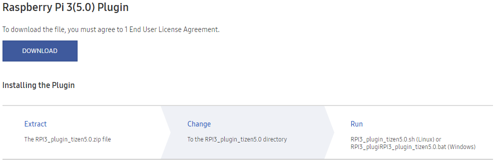
Download the plugin zip file from the Raspberry Pi 3(5.0) Plugin section at http://developer.samsung.com/tizendevice/firmware and follow the instructions.
-
For the case of the Linux shell (Linux), run the
shscript given in the instructions. For example:$ ./RPI3_plugin_tizen5.0.sh -
For the case of the Command window (Windows), run the
batscript given in the instructions. For example:> RPI3_plugin_tizen5.0.bat
-
- Raspberry Pi 3
Tips
IoT Setup Manager Details
IoT Setup Manager Features
- Saved Profiles: You can save and retrieve the configuration profiles for easy flashing.
- Three Steps Flashing:
- Select the profile.
- Select your SD Card.
- Click Burn.
- Automatic Network Connection: You can enter the Wi-Fi (SSID and password) or the Ethernet (static information) details to allow the device to automatically connect to the local network upon startup.
Prerequisites
Operating System
IoT Setup Manager supports the following operating systems:
- Windows 7 and later (64 and 32 bit)
- Ubuntu 14.04 LTS and later (64 and 32 bit)
Environment
IoT Setup Manager requires Java Runtime Environment (JRE) version 1.8 or later to be installed on your computer.
Note
You must only have the Oracle JRE installed on your computer.
Verify whether JRE is installed on your computer. To do so, open the shell terminal in Ubuntu or the command-line prompt in Windows and run the following commands:
$ java -version
java version "1.8.0_112"
Java(TM) SE Runtime Environment (build 1.8.0_112-b15)
Java HotSpot(TM) 64-Bit Server VM (build 25.112-b15, mixed mode)
If JRE is installed, the output is similar for both Ubuntu and Windows. If Java(TM) SE Runtime Environment does not appear in the output or if an error occurs, then this implies, JRE is not installed on your computer.
Ubuntu Tools
If you are using Ubuntu, the following packages must be installed in addition to the IoT Setup Manager:
- rpm2cpio
- cpio
If the packages are not installed, run the following command to install a package:
sudo apt-get install package-name
Installing IoT Setup Manager
Ensure that you have installed Tizen Studio.
To install the IoT Setup Manager using the Package Manager available in Tizen Studio:
- Open Tizen Studio and go to Tools > Package Manager.
- Click Extension SDK and verify whether the IoT Setup Manager appears in the list of available packages.
- Click install for IoT Setup Manager to install the IoT Setup Manager Extension.
- Start Tizen Studio. If Tizen Studio is already running, close and restart it.
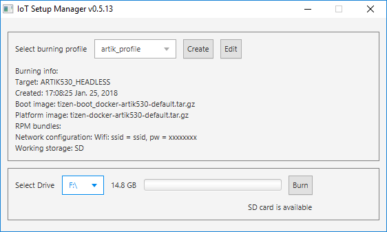
IoT Setup Manager fields
The IoT Setup Manager view contains the following fields:
-
Select burning profile
You can select one of the available profiles from the Select burning profile drop-down list, to avoid creating or modifying profiles every time. Additionally, you can copy the flashing profile to the Manager directory. This enables the application to recognize the profile on the next start.
-
Create
To create a new flashing profile.
-
Edit
To modify the existing profile.
-
Select Drive
Insert an SD card and wait until it appears in the drop-down list.
-
Burn
Click Burn and wait until the flashing routine is finished. This may take few minutes and you may have to enter your supervisor password, which is required to access the SD card.
If you want to modify the exist profile, select Edit.
The IoT Setup Manager edit view contains the following fields:
-
Profile name
Specify a profile name, for example, RPI3-headless.
-
Target
Select the board and image type from the drop-down list.
- RPI3_HEADLESS: SD-card-bootable headless image for Raspberry Pi 3 board.
-
Boot image
Browse for the Tizen Boot image available on your hard drive. You must select proper images depending on the board.
-
Platform image
Browse for the Tizen Platform image available on your hard drive. You must select proper images depending on the board.
-
RPM bundles (optional)
Browse for the folder that contains the Tizen RPMs on your hard drive. You do not have to enter the details in this field.
-
Network configuration (optional)
Enter the Wi-Fi (SSID and password) or the Ethernet (static) details to allow the device to automatically connect to the local network after startup. If you do not want to set up the network, you can clear the Wifi and the Ethernet check box.
Tips and Guidelines
- Profiles are an easy way to store image paths and network configuration information. After you save a profile, you can use it to flash your SD Card instead of specifying all information again.
- While creating or editing a profile, ensure that the boot images, platform images, and the rpms (if selected) match the target device.
- Ensure that there are no white spaces in the boot image, platform image, and the rpm folder paths.
- Place RPMs in a separate directory, which does not contain any other files or directories and select the directory path for creating the profile.
Flashing through Command Line
You can also flash the SD card through command-line in Linux computer instead of using IoT Setup Manager. To flash the SD card for Raspberry Pi 3 without IoT setup Manager:
-
Complete the following prerequisites:
-
Install the
pvpackage in the Linux computer:$ sudo apt-get install pv -
Ensure that you have an SD card of 4 GB or more.
-
Verify whether the binary image files are in your computer. .
-
Fusing-script for Raspberry Pi 3:
$ wget https://git.tizen.org/cgit/platform/kernel/u-boot/plain/scripts/tizen/sd_fusing_rpi3.sh?h=tizen --output-document=sd_fusing_rpi3.sh
$ chmod 755 sd_fusing_rpi3.sh
-
-
Flash the SD card to ensure it is ready to be used for Tizen:
-
Insert an SD card to the Linux computer and verify its device node.
Note
To verify the device node:
-
Run the following command before inserting the SD card into the Linux computer:
$ ls -al /dev/sd*For example:
$ ls -al /dev/sd* brw-rw---- 1 root disk 8, 0 9 18 09:08 /dev/sda brw-rw---- 1 root disk 8, 1 9 18 09:08 /dev/sda1 brw-rw---- 1 root disk 8, 2 9 18 09:08 /dev/sda2 brw-rw---- 1 root disk 8, 5 9 18 09:08 /dev/sda5 -
Insert the SD card and type the same command again:
$ ls -al /dev/sd*For example:
$ ls -al /dev/sd*
brw-rw---- 1 root disk 8,  0  9 18 09:08 /dev/sda
brw-rw---- 1 root disk 8,  1  9 18 09:08 /dev/sda1
brw-rw---- 1 root disk 8,  2  9 18 09:08 /dev/sda2
brw-rw---- 1 root disk 8,  5  9 18 09:08 /dev/sda5
brw-rw---- 1 root disk 8, 16  9 22 14:59 /dev/sdb
brw-rw---- 1 root disk 8, 17  9 22 14:59 /dev/sdb1
brw-rw---- 1 root disk 8, 18  9 22 14:59 /dev/sdb2
brw-rw---- 1 root disk 8, 19  9 22 14:59 /dev/sdb3
brw-rw---- 1 root disk 8, 20  9 22 14:59 /dev/sdb4
brw-rw---- 1 root disk 8, 21  9 22 14:59 /dev/sdb5
brw-rw---- 1 root disk 8, 22  9 22 14:59 /dev/sdb6
brw-rw---- 1 root disk 8, 23  9 22 14:59 /dev/sdb7
The new
sdXnode (where X is a letter) is the device node for the SD card.In this example, the device node for the SD card is
sdb.
-
-
Download and unzip the flash-sdcard-rpi3.tar.gz script file. Ensure that this script and all other downloaded files are in the same directory.
Note
The file extension of the downloaded file is
.tar_.gz. Modify it to.tar.gzbefore unzipping the file. -
Run the
flash-sdcard.shscript with the device node and binary version:$ sudo ./flash-sdcard.sh <SD card device node>For example:
$ sudo ./flash-sdcard.sh /dev/sdb
-
-
Open the Smart Development Bridge (SDB) connection. For more information, see Setting up Raspberry Pi 3.
Note
Repeat
sdb connect 192.168.1.11in the Linux shell (Linux) or the command window (Windows) whenever you power cycle the device, in order to reconnect the SDB tool.
Setting up Wi-Fi
This section is not applicable if you want to connect your device to the SmartThings Cloud. In case of SmartThings devices, the device enables SoftAP mode during setup, therefore, you need not switch to Wi-Fi separately.
You can set up a Wi-Fi connection by running wifi_manager_test and entering the options 1 > 3 > 9 > b > c. If you set up the connection once, it reconnects automatically the next time you power cycle the device.
# wifi_manager_test
Test Thread created...<Enter>
Event received from stdin
Network Connection API Test App
Options..
1   - Wi-Fi init and set callbacks
2   - Wi-Fi deinit(unset callbacks automatically)
3   - Activate Wi-Fi device
4   - Deactivate Wi-Fi device
5   - Is Wi-Fi activated?
6   - Get connection state
7   - Get MAC address
8   - Get Wi-Fi interface name
9   - Scan request
a   - Get Connected AP
b   - Get AP list
c   - Connect
d   - Disconnect
e   - Connect by wps pbc
f   - Forget an AP
g   - Set & connect EAP
h   - Set IP method type
i   - Set Proxy method type
j   - Get Ap info
k   - Connect Specific AP
l   - Load configuration
m   - Save configuration
n   - Remove configuration
o   - TDLS Discover
p   - TDLS Connect
q   - TDLS Connected peer
r   - TDLS Disconnect
s   - Connect Hidden AP
t   - Connect WPS PBC without SSID
u   - Connect WPS PIN without SSID
v   - Cancel WPS Request
w   - Set Auto Scan Enable-Disable
x   - Set Auto Scan Mode
y   - Get wifi scanning state
z   - Get Auto Scan Enable-Disable
A   - Get Auto Scan Mode
B   - Enable TDLS Channel Switch Request
C   - Disable TDLS Channel Switch Request
D   - Get Wi-Fi Module State
E   - BSSID Scan
F   - Add VSIE
G   - Get VSIE
H   - Remove VSIE
I   - Start Multi Scan
J   - Flush BSS
K   - Set auto connect mode
L   - Get auto connect mode
0   - Exit
ENTER  - Show options menu.......
Operation succeeded!
1
Event received from stdin
Wifi init succeeded
Operation succeeded!
3
Event received from stdin
Wi-Fi Activation Succeeded
Operation succeeded!
9
Event received from stdin
Interface name : wlan0
Operation succeeded!
b
Event received from stdin
AP name : crash_messaging, state : Disconnected
AP name : dnet1, state : Disconnected
... < list of APs > ...
Get AP list finished
Operation succeeded!
Background Scan Completed, error code : NONE
c
Event received from stdin
Input a part of AP name to connect : <AP name>
Passphrase required : TRUE
Input passphrase for dnet1 : <Password>